Fillable Printable Report Form of Electrical Installation Condition
Fillable Printable Report Form of Electrical Installation Condition
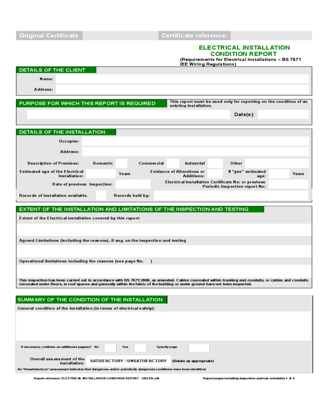
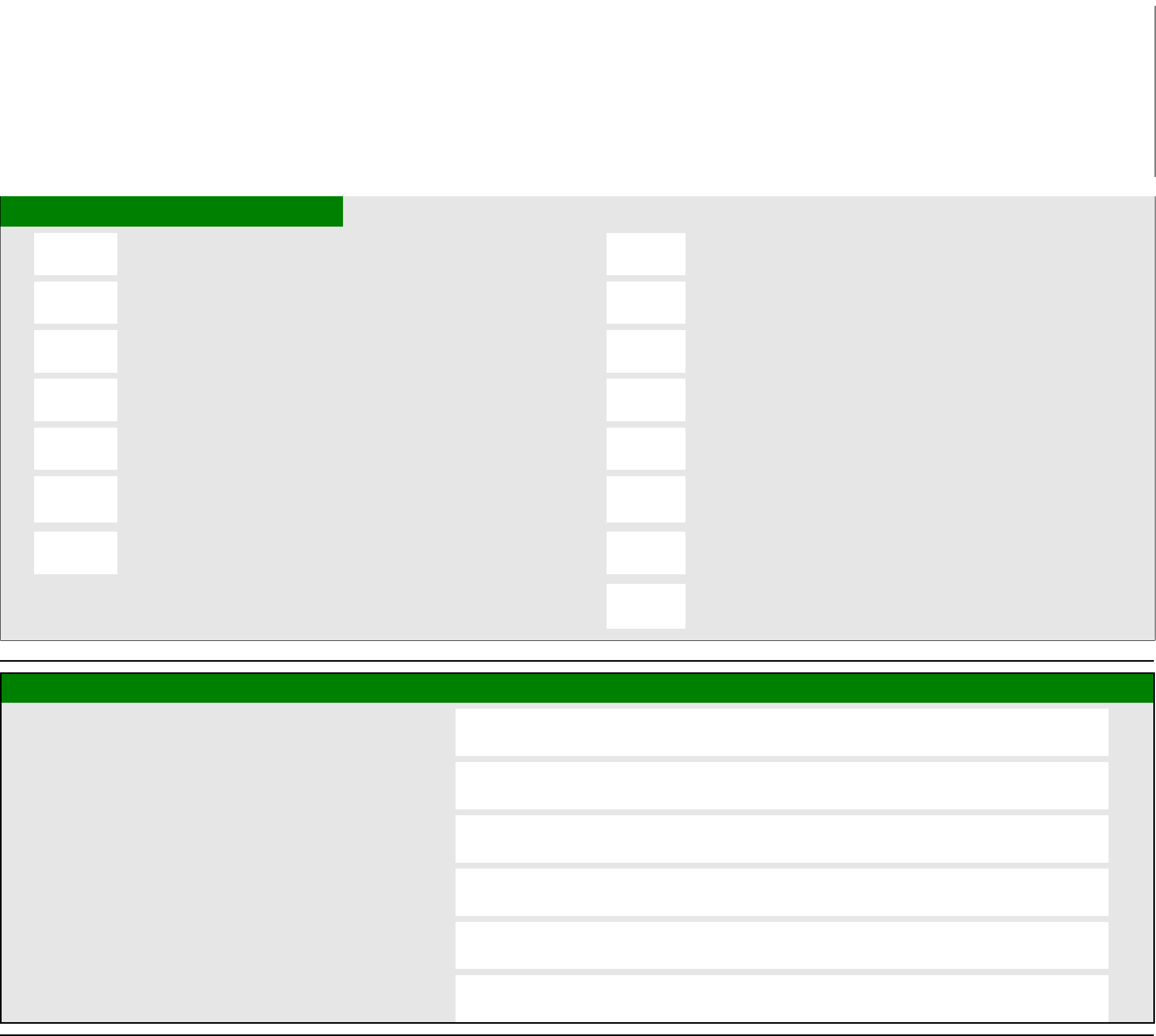
Report Form of Electrical Installation Condition

Original Certificate Certificate reference:
ELECTRICAL INSTALLATION
CONDITION REPORT
(Requirements for Electrical Installations – BS 7671
IEE Wiring Regulations)
DETAILS OF THE CLIENT
Name:
Address:
PURPOSE FOR WHICH THIS REPORT IS REQUIRED
This report must be used only for reporting on the condition of an
existing installation.
Date(s):
DETAILS OF THE INSTALLATION
Occupier:
Address:
Description of Premises: Domestic
Commercial
Industrial
Other
Estimated age of the Electrical
Installation:
Years
Evidence of Alterations or
Additions:
If “yes” estimated
age:
Years
Date of previous Inspection:
Electrical Installation Certificate No: or previous
Periodic Inspection report No:
Records of installation available. Records held by:
EXTENT OF THE INSTALLATION AND LIMITATIONS OF THE INSPECTION AND TESTING
Extent of the Electrical installation covered by this report:
Agreed Limitations (including the reasons), if any, on the inspection and testing
Operational limitations including the reasons (see page No. )
This inspection has been carried out in accordance with BS 7671:2008, as amended. Cables concealed within trunking and conduits, or cables and conduits
concealed under floors, in roof spaces and generally within the fabric of the building or under ground have not been inspected.
SUMMARY OF THE CONDITION OF THE INSTALLATION
General condition of the installation (in terms of electrical safety):
If necessary, continue on additional page(s)? No
Yes
Specify page
Overall assessment of the
installation:
SATISFACTORY / UNSATISFACTORY
(Delete as appropriate)
An “Unsatisfactory” assessment indicates that dangerous and/or potentially dangerous conditions have been identified.
Report reference: ELECTRICAL INSTALLATION CONDITION REPORT - GREEN.odt Report pages including inspection and test schedules 1 of 9
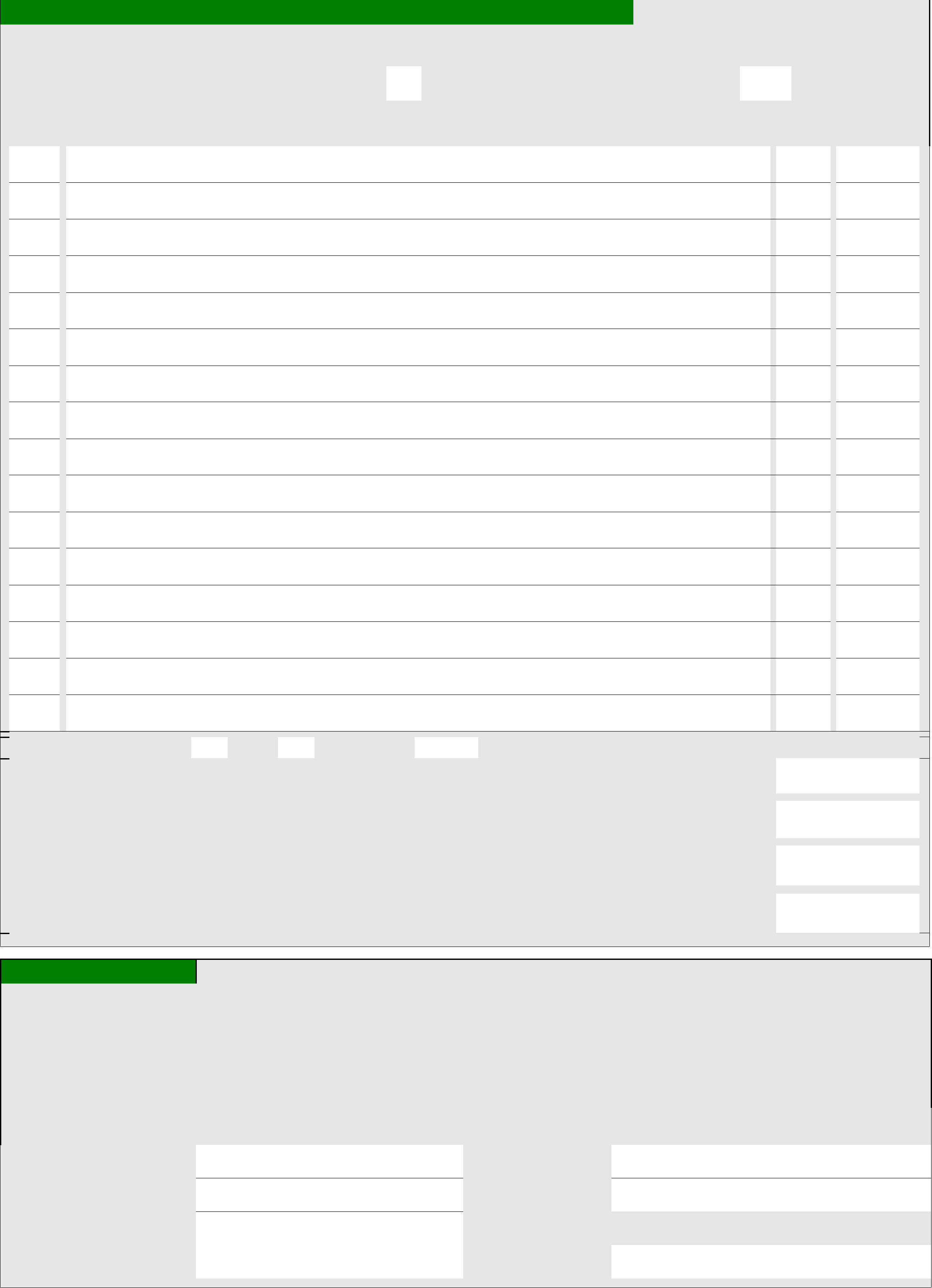
OBSERVATION AND RECOMMENDATIONS FOR ACTIONS TO BE TAKEN
Referring to the attached Schedules of Inspection and Test Results and subject to the limitations;
There are no item adversely affecting electrical safety,
or
The following observations and
recommendations for
N/A are made
Item No *Code
Investigation
required?
1
Additional Pages? No
Yes
Specify page
*One of the following codes, as appropriate, has been allocated to each of the observations made above to
indicate to the person(s) responsible for the installation the degree of urgency for remedial action:
Code C1 "Danger Present". Risk of injury. Immediate remedial action required.
Code C2 "Potentially dangerous". Urgent remedial action required.
Code C3 "Improvement recommended".
Please see the notes for recipient for guidance regarding the Classification codes.
Immediate remedial action
required for items:
Urgent remedial action
required for items:
Further investigation
required for items:
Improvement
recommended for items:
DECLARATION
I/We, being the person(s) responsible for the inspection and testing of the electrical installation (as indicated by my/our signature(s) below, particulars of
which are described above, having exercised reasonable skill and care when carrying out the inspection and testing, hereby Certify that the information on
this report, including the observations and the attached schedules, provides an accurate assessment of the condition of the electrical installation taking into
account the stated extent of the installation and the limitation of the inspection and testing.
I/We further declare that in my/our judgement, the said installation was overall in condition at the time of the inspection we carried out,
and that it should be further inspected as recommended.
INSPECTION, TESTING AND ASSESSMENT BY: REPORT REVIEWED AND CONFIRMED BY:
Signature:
Signature:
Name : (CAPITALS)
Name : (CAPITALS)
Position:
(Registered Qualified Supervisor for the approved contractor at J)
Date:
Date:
Report reference: ELECTRICAL INSTALLATION CONDITION REPORT - GREEN.odt Report pages including inspection and test schedules 2 of 9

SCHEDULES AND ADDITIONAL PAGES
Schedule of items inspected Page No. 4,5,6,7
Additional pages, including additional source(s)
data sheets: Page No(s):
Schedule of Circuit Details for the installation:
Page No(s):
8
Schedule of Test Results for the installation:
Page No(s):
The pages identified here form an essential part of this report. The report is valid only if accompanied by all the schedules and additional pages identified above.
NEXT INSPECTION
We recommend that this installation is further inspected and tested after an interval of not more than
Provided that any items which have been attributed a Recommendation Code C1 and C2 (require urgent attention) are remedied without
delay and as soon as possible respectively. Items which have been attributed a Recommendation Code C3 should be actioned as soon as
practicable (see F).
DETAILS OF ELECTRICALCONTRACTOR
Trading Title:
Address:
Telephone number:
Fax number:
Registration number
Postcode: Branch number:
(if applicable)
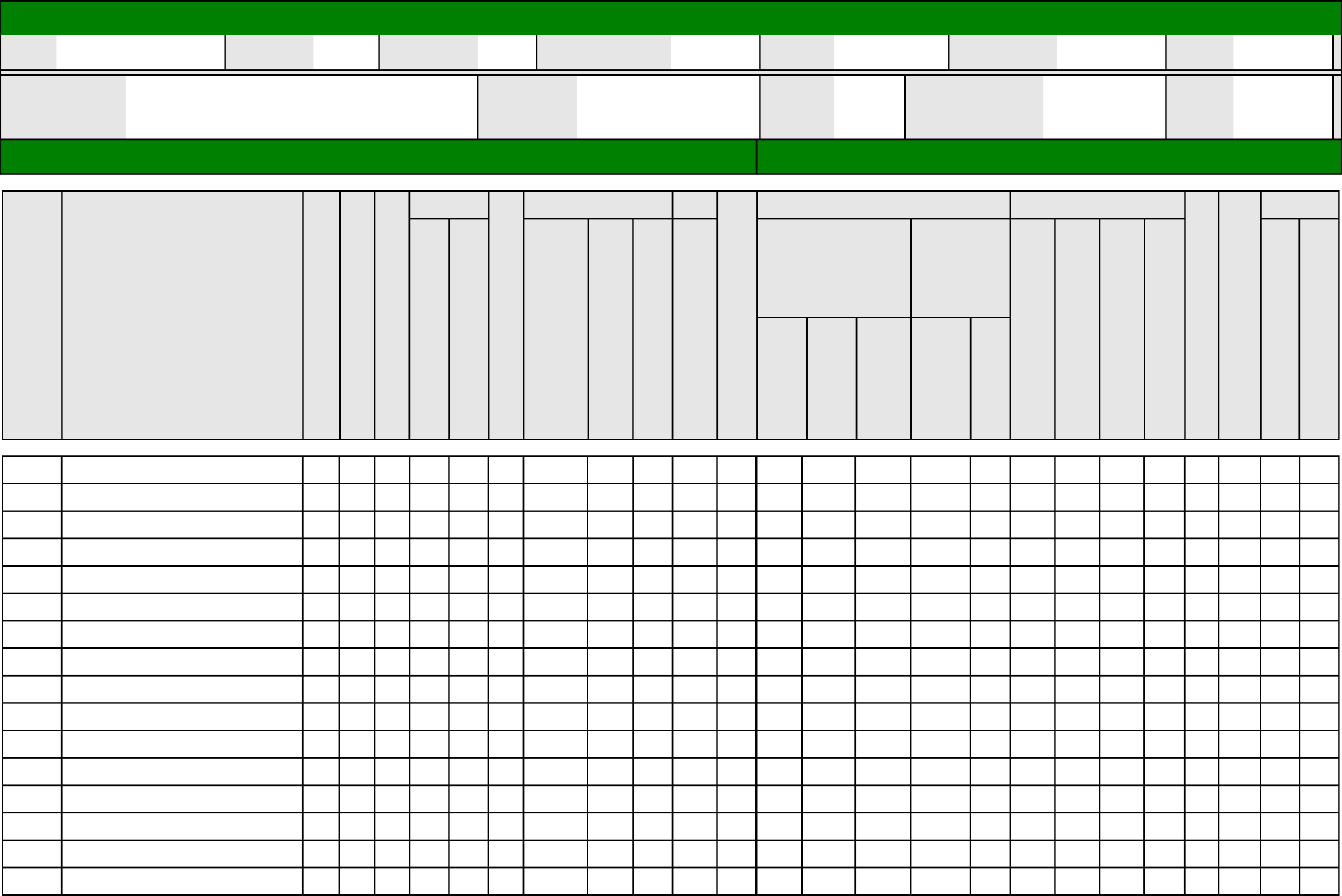
SUPPLY CHARACTERISTICS AND EARTHING ARRANGEMENTS
Tick boxes and enter details, as appropriate
◊ System
Type(s)
◊ Number and Type of
Live Conductors
Nature of Supply
Parameters
◊ Characteristics of Primary
supply Overcurrent
Protective Device(s)
TN-S
TN-C-S
TN-C
TT
IT
AC DC
1-phase
(2 wire)
1-phase
(3 wire)
2-phase
(3 wire)
3-phase
(3 wire)
3-phase
(4 wire)
2 pole
3 pole other
Other
(Please state)
Nominal
Voltage U (1)
V
Nominal
frequency f
(1)
Hz
Prospective
fault current
(2/3)
kA
External earth fault
loop impedance Ze
(3/4)
Ω
Number of
supplies 1) by enquiry
NOTES: (2) by enquiry or
by measurement
BS(EN)
Type
Rated
current
A
Short-circuit
capacity
kA
(3) where more than one
supply, the higher or highest
values
(4) by measurement
PARTICULARS OF INSTALLATION AT THE ORIGIN
Tick boxes and enter details, as appropriate
Means of earthing Details Installation Earth Electrode (where applicable)
Distributor's
facility
Type:
(eg rod(s), tape etc)
Location:
Maximum
Demand:
kVA/Amps
Installation
earth electrode
Electrode
resistance, RA:
Ω
Method of
measurement:
Protective measures against electric
Shock:
# Main Switch or Circuit Breaker Earthing and Protective Bonding Conductors
Type (BS(EN) Voltage Rating V Earthing conductor Conductor csa mm
2
No of Poles Rated current I n A Conductor material Continuity check (√)
Supply
conductors:
material
RCD operating
current I∆n
mA
Bonding of extraneous-conductive-parts (√)
Gas service Lighting
Supply
conductors:
csa
mm
2
RCD operating
time (at I∆n)
ms
Water service Structural steel
Oil service Other service(s)
Report reference: ELECTRICAL INSTALLATION CONDITION REPORT - GREEN.odt Report pages including inspection and test schedules 3 of 9
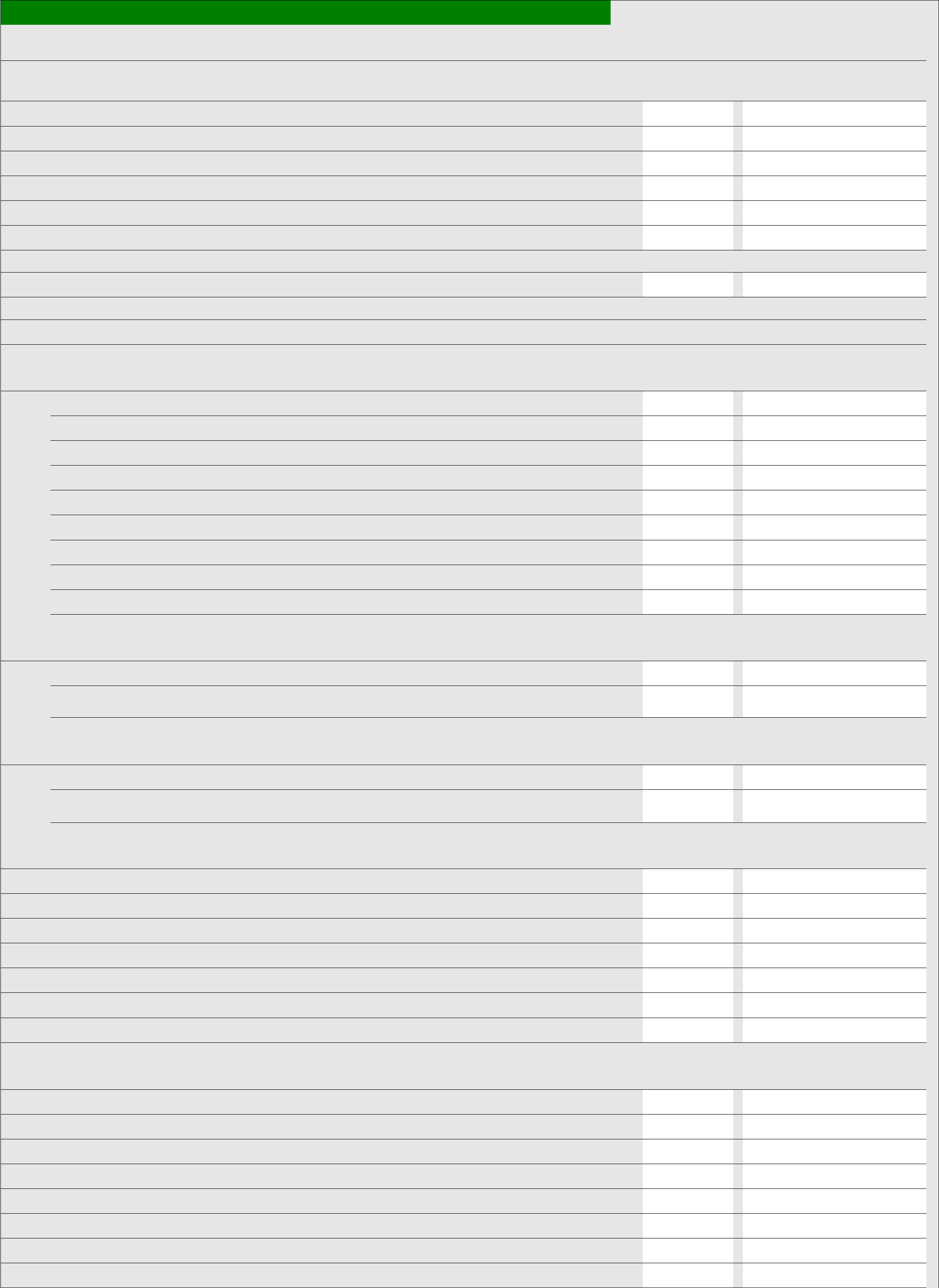
INSPECTION SCHEDULE FOR DISTRIBUTION BOARDS AND CIRCUITS
Item Description Outcome* Location reference
1.0 Condition/adequacy of distributor’s supply intake equipment
1.1 Service cable
1.2 Service cut-out/fuse(s)
1.3 Meter tails - distributor
1.4 Meter tails - consumer
1.5 Metering equipment
1.6 Means of main isolation (where present)
2.0 Presence of adequate arrangements for parallel or switched alternative sources
3.0 Automatic disconnection of supply
3.1 Main earthing and bonding arrangements
* Presence and condition of distributor’s earthing arrangement
* Presence and condition of earth electrode arrangement
* Adequacy of earthing conductor size
* Adequacy of earthing conductor connections
* Accessibility of earthing conductor connections
* Adequacy of main protective bonding conductor size(s)
* Adequacy of main protective bonding conductor connections
* Accessibility of main protective bonding connections
* Provision of earthing/bonding labels at all appropriate locations
3.2 FELV
* Source providing at least simple separation
* Plugs, socket-outlets and the like not interchangeable with those of other systems within the
premises
3.3 Reduced low voltage
* Adequacy of source
* Plugs, socket-outlets and the like not interchangeable with those of other systems within the
premises
4.0 Other methods of protection (where the methods of protection listed below are employed, details should be provided on separate sheets)
4.1 Double insulation
4.2 Reinforced insulation
4.3 Use of obstacles
4.4 Placing out of reach
4.5 Non-conducting location
4.6 Earth-free local equipotential bonding
4.7 Electrical separation for more than one item of equipment
5. 0 Distribution equipment
5.1 Adequacy of working space/accessibility of equipment
5.2 Security of fixing
5.3 Condition of insulation of live parts
5.4 Adequacy/security of barriers
5.5 Condition of enclosure(s) in terms of IP rating
5.6 Condition of enclosure(s) in terms of fire rating
5.7 Enclosure not damaged/deteriorated so as to impair safety
5.8 Presence of main switch(es), linked where required
Report reference: ELECTRICAL INSTALLATION CONDITION REPORT - GREEN.odt Report pages including inspection and test schedules 4 of 9

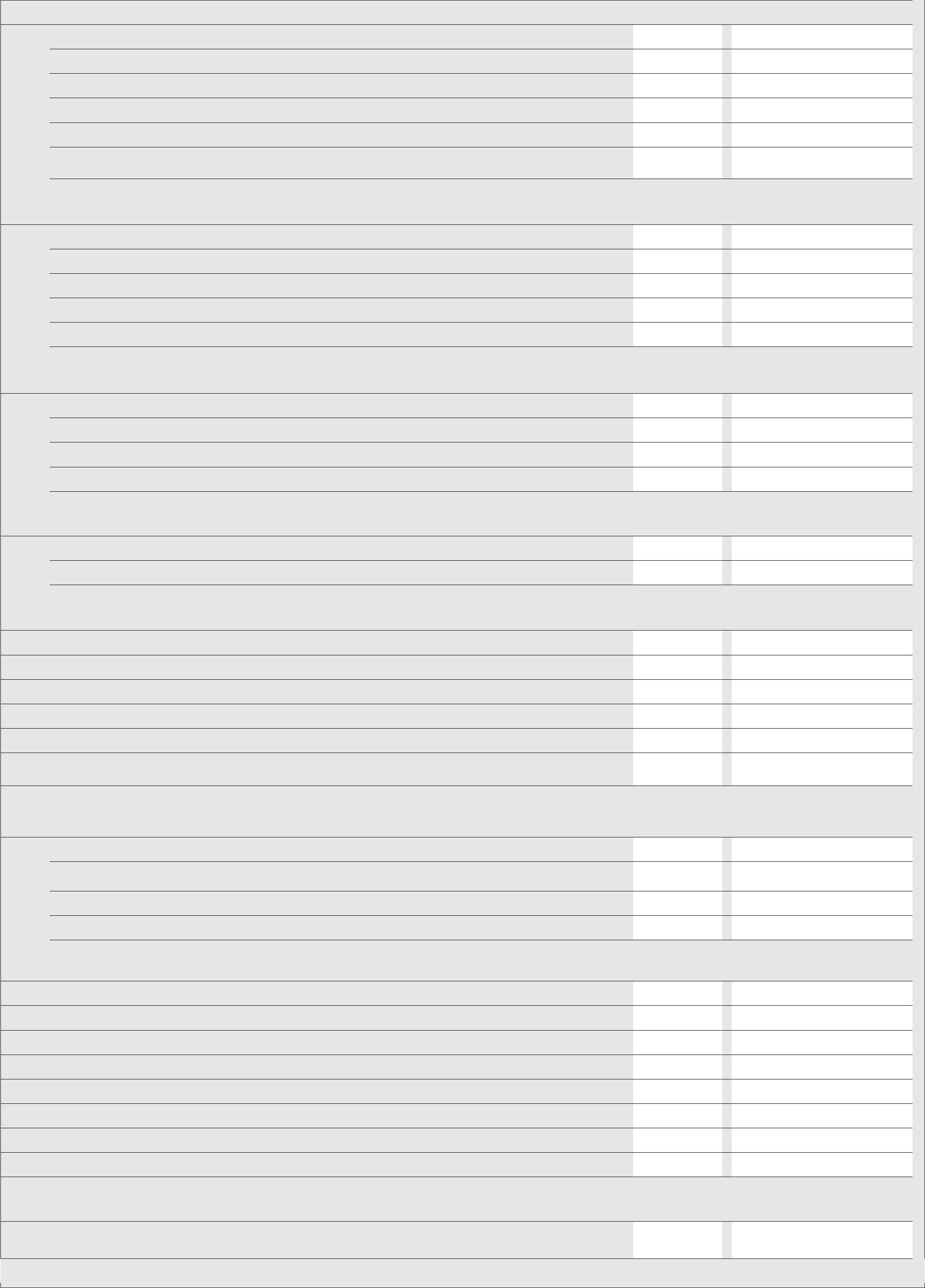
5.9 Operation of main switch(es) (functional check)
5.10 Correct identification of circuit protective devices
5.11 Adequacy of protective devices for prospective fault current
5.12 RCD(s) provided for fault protection – includes RCBOs
5.13 RCD(s) provided for additional protection – includes RCBOs
5.14 RCD(s) provided for protection against fire – includes RCBOs
5.15 Manual operation of circuit-breakers and RCDs to prove disconnection
5.16 Presence of RCD retest notice at or near equipment where required
5.17 Presence of diagrams, charts or schedules at or near equipment where required
5.18
Presence of non-standard (mixed) cable colour warning notice at or near equipment where
required
5.19
Presence of alternative supply arrangement warning notice(s) at or near equipment where
required
5.20 Presence of replacement next inspection recommendation label
5.21 Presence of other required labelling (specify)
5.22
Examination of protective device(s) and base(s); correct type and rating (no signs of unacceptable
thermal damage, arcing or overheating)
5.23 Protection against mechanical damage where cables enter equipment
5.24 Protection against electromagnetic effects where cables enter metallic enclosures
6.0 Distribution/final circuits
6.1 Identification of conductors
6.2 Cables correctly supported throughout their length
6.3 Condition of insulation of live parts
6.4 Non-sheathed cables protected by enclosure in conduit, duct or trunking
6.5 Suitability of containment systems for continued use (including flexible conduit)
6.6 Cables correctly terminated in enclosures (indicate extent of sampling in Section D of report)
6.7 Examination of cables for signs of unacceptable thermal and mechanical damage/deterioration
6.8 Adequacy of cables for current-carrying capacity with regard to the type and nature of installation
6.9 Adequacy of protective devices; type and rated current for fault protection
6.10 Presence and adequacy of circuit protective conductors
6.11 Co-ordination between conductors and overload protective devices
6.12
Cable installation methods/practices appropriate to the type and nature of installation and external
influences
6.13 Cables where exposed to direct sunlight, of a suitable type
6.14 Concealed cables installed in prescribed zones (see extent and limitations)
6.15
Concealed cables incorporating earthed armour or sheath, or run within earthed wiring system,or
otherwise protected against mechanical damage caused by nails, screws and the like where not
in prescribed zones or not protected by 30 mA RCD (see extent and limitations)
6.16 Provision of additional protection by 30 mA RCD for cables concealed in walls or partitions
6.17 Provision of additional protection by 30 mA RCD
* Where reasonably likely to be used to supply mobile equipment for use outdoors
* For all socket-outlets of rating 20 A or less provided for use by ordinary persons
6.18 Provision of fire barriers, sealing arrangements and protection against thermal effects
6.19 Band II cables segregated/separated from Band I cables
6.20 Cables segregated/separated from non-electrical services
6.21
Termination of cables at enclosures (identify numbers and locations of items inspected in Section
D)
* Connections under no undue strain
No basic insulation of a conductor visible outside an enclosure
Connections of live conductors adequately enclosed
Adequacy of connection at point of entry to enclosure (gland, bush or similar)
6.22 General condition of wiring systems
6.23 Temperature rating of cable insulation
6.24 Condition of accessories including socket-outlets, switches and joint boxes
6.25 Suitability of accessories for external influences
7.0 Isolation and switching
Report reference: ELECTRICAL INSTALLATION CONDITION REPORT - GREEN.odt Report pages including inspection and test schedules 5 of 9
7.1 Isolations
* presence and condition of appropriate devices
* acceptable location
* capable of being secured in the OFF position
* correct operation verified
* clearly identified by position and/or durable marking(s)
* Warning label posted in situations where live parts cannot be isolated by the operation of a
single device
7.2 Switching off for mechanical maintenance
* presence and condition of appropriate devices
* acceptable location
* capable of being secured in the OFF position
* correct operation verified
* clearly identified by position and/or durable marking(s)
7.3 Emergency switching/stopping
* presence and condition of appropriate devices
* readily accessible for operation where danger might occur
* correct operation verified
* clearly identified by position and/or durable marking(s)
7.4 Functional switching
* presence and condition of appropriate devices
* correct operation verified
8.0 Current-using equipment (permanently connected)
8.1 Condition of equipment in terms of IP rating
8.2 Equipment does not constitute a fire hazard
8.3 Enclosure not damaged/deteriorated so as to impair safety
8.4 Suitability for the environment and external influences
8.5 Security of fixing
8.6
Cable entry holes in ceiling above luminaries, sized or sealed so as to restrict the spread of fire
(indicate extent of sampling in Section D of report)
8.7 Recessed luminaires (e.g. downlighters)
* correct type of lamps fitted
* installed to minimise build-up of heat by use of “fire rated” fittings,insulation displacement box
or similar
* no signs of overheating to surrounding building fabric
* no signs of overheating to conductors/terminations
9.0 Location(s) containing a bath or shower
9.1 Additional protection for all low voltage (LV) circuits by RCD not exceeding 30 mA
9.2 Where used as a protective measure, requirements for SELV or PELV are met
9.3 Shaver sockets comply with BS EN 61558-2-5 or BS 3535
9.4 Presence of supplementary bonding conductors unless not required by BS 7671: 2008
9.5 Low voltage (e.g. 230 volts) socket-outlets sited at least 3 m from zone 1
9.6 Suitability of equipment for external influences for installed location in terms of IP rating
9.7 Suitability of equipment for installation in a particular zone
9.8 Suitability of current-using equipment for a particular position within the location
10.0 Other Special installations or locations
List special locations present, if any. List the results of particular inspections applied.– a separate
page is required for each location
Report reference: ELECTRICAL INSTALLATION CONDITION REPORT - GREEN.odt Report pages including inspection and test schedules 6 of 9
* All Boxes must be completed Unacceptable condition state C1 or C2 Outcome
√
Indicates Acceptable condition Improvement recommended state C3
Provide additional comment where
appropriate on attached numbered
sheets. C1, C2 and C3 coded items to
be recorded in section F of the report.
LIM indicates a limitation
Further investigation required state F/I
(to determine whether danger or potential
(danger exists)
N/A indicates Not applicable
SCHEDULE OF ITEMS TESTED
External earth loop impedance, Ze
Basic protection against direct contact by barrier or
enclosure provided during erection
Installation earth electrode resistance, Ra
Insulation of non-conducting floors or walls
Continuity of protective conductors
Polarity
Continuity of ring circuit conductors
Earth fault loop impedance Zs
Insulation resistance between live conductors
Verification of phase sequence
Insulation resistance between live conductors and earth
Operation of residual current devices
Protection by separation of circuits
Functional testing of assemblies
Verification of voltage drop
TEST INSTRUMENTS USED
Earth fault loop impedance
Insulation resistance
Continuity
RCD
Other N/A
Other N/A
NOTES FOR RECIPIENT
THIS CERTIFICATE IS A VALUABLE DOCUMENT AND SHOULD BE RETAINED FOR FUTURE REFERENCE
This Electrical Installation Condition Report form is intended for the reporting on the condition of an existing electrical installation.
You should have received an original Certificate and the contractor should have retained a duplicate. If you were the person ordering
this report, but not the owner of the installation, you should pass this Report, or a full copy of it, immediately to the user.
The original Report is to be retained in a safe place and be shown to any person inspecting or undertaking further work on the electrical
installation in the future. If you later vacate the property, this Report will provide the new owner with the details of the condition of the
electrical installation at the time the Report was issued.
The ‘Extent and Limitations’ box should fully identify the extent of the installation covered by this Report and any limitations on the
inspection and tests. The contractor should have agreed these aspects with you and any interested parties (Licensing Authority,
Insurance Company, Building Society etc) before the inspection was carried out.
The Report will usually contain a list of recommended actions necessary to bring the installation up to the current standard. For items
classified as ‘requires urgent attention’, the safety of those using the installation may be at risk, and it is recommended that a
competent person undertake the necessary remedial work without delay.
For safety reasons, the electrical installation will need to be inspected at appropriate intervals by a competent person. The maximum
time interval recommended before the next inspection is stated in the Report under “Next Inspection.”
Report reference: ELECTRICAL INSTALLATION CONDITION REPORT - GREEN.odt Report pages including inspection and test schedules 7 of 9
DISTRIBUTION BOARD DETAILS
DB
ref.:
Z
s
at this
board (Ω):
I
pf
at this
board (KA):
Main switch type
BSEN reference:
Rating:
Amps
Supply
conductors:
mm
2
Earth:
mm
2
Distribution
board location:
Supplied
from:
No. Of
phases:
Supply protective
device type:
BSEN reference:
Rating:
Amps
CIRCUIT DETAILS TEST RESULTS
Circuit Reference
Circuit designation
Type of wiring
Reference method
Number of points served
Circuit
conductors
Live (mm
2
)
cpc (mm
2
)
Max.Disconnection time permitted (s)
Overcurrent devices RCD
Type BS EN
Rating (A)
Short circuit capacity (KA)
IΔn mA
Maximum permitted Zs Ω
Circuit impedances Ω Insulation resistance
Ring final circuits
only (Measured end
to end)
All circuits
(At least
one column
to be
completed)
r
1
r
n
r
2
R
1 +
R
2
R
2
Phase /Phase M Ω
Phase /Neutral M Ω
Phase /Earth M Ω
Neutral /Earth M Ω
Polarity
Maximum Measured Zs Ω
RCD
At IΔn ms
At 5 x IΔn ms
Report reference: ELECTRICAL INSTALLATION CONDITION REPORT - GREEN.odt Report pages including inspection and test schedules 8 of 9

CODES FOR TYPES OF WIRING
A B C D E F G H O (other please state)
PVC/PVC
CABLES
PVC CABLES IN
METALLIC
CONDUIT
PVC CABLES IN
NON-METALIC
CONDUIT
PVC CABLES IN
METALIC
TRUNKING
PVC CABLES IN
NON-METALIC
TRUNKING
PVC/SWA
CABLES
XLPE/SWA
CABLES
MINERAL-
INSULATED CABLES
Report reference: ELECTRICAL INSTALLATION CONDITION REPORT - GREEN.odt Report pages including inspection and test schedules 9 of 9