Fillable Printable Sample Electrical Installation Condition Report Form
Fillable Printable Sample Electrical Installation Condition Report Form
Sample Electrical Installation Condition Report Form
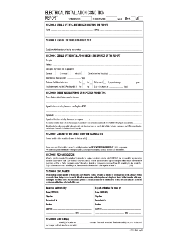
SECTION A: DETAIlS Of ThE ClIENT / pErSON OrDErINg ThE rEpOrT
Name .......................................................................................................... Address ..........................................................................................................
................................................................................................................................................................................................................................................
SECTION C: DETAIlS Of ThE INSTAllATION whICh IS ThE SubjECT Of ThIS rEpOrT
Occupier ................................................................................................................................................................................................................................
Address ................................................................................................................................................................................................................................
Description of premises (tick as appropriate)
Domestic Commercial Industrial Other (include brief description) ...................................................................................
Estimated age of wiring system ................................... years
Evidence of additions / alterations Yes
No Not apparent If yes, estimate age ................................... years
Installation records available? (Regulation 621.1) Yes
No Date of last inspection ................................... (date)
SECTION g: DEClArATION
I/we being the person(s) responsible for the inspection and testing of the electrical installation (as indicated by my/our signatures below), particulars of which
are described above, having exercised reasonable skill and care when carrying out the inspection and testing, hereby declare that the information in this report,
including the observations and the attached schedules, provides an accurate assessment of the condition of the electrical installation taking into account the
stated extent and limitations in Section D of this report.
Inspected and tested by:
Name (CApITAlS): ................................................................................
Signature: ...............................................................................................
for/on behalf of: ....................................................................................
position: .................................................................................................
Address: ..................................................................................................
....................................................................... Date: ..............................
SECTION b: rEASON fOr prODuCINg ThIS rEpOrT
................................................................................................................................................................................................................................................
Date(s) on which inspection and testing was carried out ......................................................................................................................................................
SECTION D: ExTENT AND lImITATIONS Of INSpECTION AND TESTINg
Extent of electrical installation covered by this report ............................................................................................................................................................
................................................................................................................................................................................................................................................
Agreed limitations including the reasons (see Regulation 634.2) ..........................................................................................................................................
................................................................................................................................................................................................................................................
Agreed with: ...........................................................................................................................................................................................................................
Operational limitations including the reasons (see page no. ............ ) ..................................................................................................................................
The inspection and testing detailed in this report and accompanying schedules have been carried out in accordance with BS 7671:2008 (IET Wiring Regulations) as amended to ............................
It should be noted that cables concealed within trunking and conduits, under oors, in roof spaces and generally within the fabric of the building or underground, have NOT been inspected unless
specically agreed between the client and inspector prior to inspection.
SECTION E: SummAry Of ThE CONDITION Of ThE INSTAllATION
General condition of the installation (in terms of electrical safety) ........................................................................................................................................
................................................................................................................................................................................................................................................
Overall assessment of the installation in terms of its suitability for continued use SATISfACTOry / uNSATISfACTOry * (delete as appropriate).
* An unsatisfactory assessment indicates that dangerous (code C1) and/or potentially dangerous (code C2) conditions have been identied.
SECTION f: rECOmmENDATIONS
Where the overall assessment of the suitability of the installation for continued use above is stated as UNSATISFACTORY, I/we recommend that any observations
classed as ‘Danger present’ (code C1) or ‘Potentially dangerous’ (code C2) are acted upon as a matter of urgency. Investigation without delay is recommended for
observations identied as ‘Further investigation required’. Observations classied as ‘Improvements recommended’ (code C3) should be given due consideration.
Subject to the necessary remedial action being taken, I/we recommend that the installation is further inspected and tested by ................................... (date).
report authorised for issue by:
Name (CApITAlS): ................................................................................
Signature: ...............................................................................................
for/on behalf of: ....................................................................................
position: .................................................................................................
Address: ..................................................................................................
....................................................................... Date: ..............................
SECTION h: SChEDulE(S)
................................... schedule(s) of inspection and ................................... schedule(s) of test results are attached. The attached schedule(s) are part of this document
and this report is valid only when they are attached to it.
C-EICR5 REV V1 Aug 2011
ElECTrICAl INSTAllATION CONDITION
rEpOrT Certicate number: Registration number: (optional) Sheet of
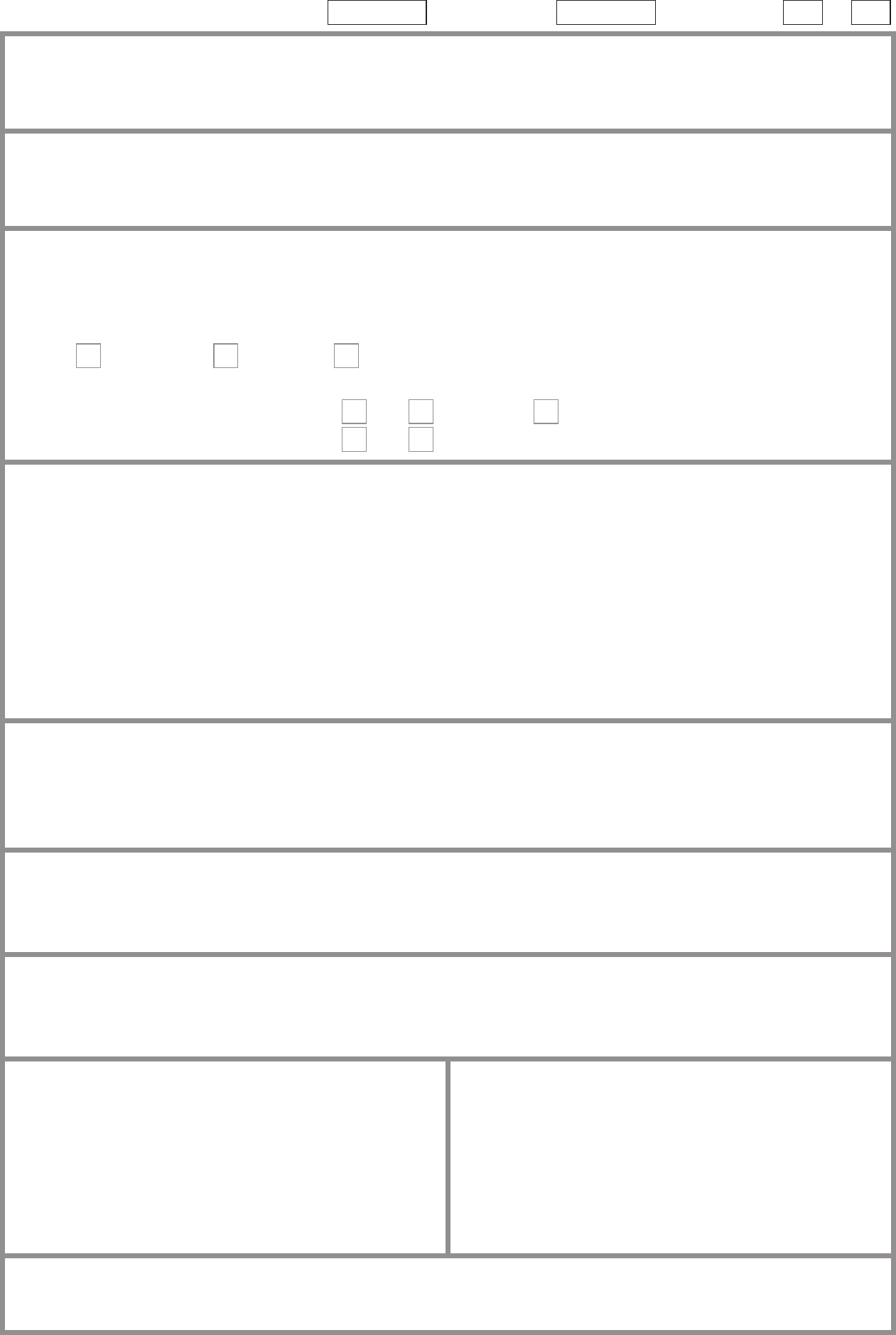
SECTION I: Supply ChArACTErISTICS AND EArThINg ArrANgEmENTS
Earthing arrangements Number and type of live conductors Nature and type of supply parameters Supply protective device
TN-C
TN-S
TN-C-S
TT
IT
a.c.
d.c.
1-phase, 2 wire
2-wire
2-phase, 3 wire
3-wire
3-phase, 3 wire
3-phase, 4 wire
Conrmation of supply polarity
Nominal voltage, U / U
o
(1)
.......................... V
Nominal frequency, f
(1)
............................. Hz
Prospective fault current, I
pf
(2)
................... kA
External loop impedance, Ze
(2)
.................. Ω
Note: (1) by enquiry. (2) by enquiry or measurement
BS (EN) ....................................
Type ..........................................
Rated current ......................... A
Other sources of supply (as detailed on attached schedule)
SECTION j: pArTICulArS Of INSTAllATION rEfErrED TO IN rEpOrT
means of earthing Details of Earth Electrode (where applicable)
Distributor’s facility
Installation earth
electrode
Type .......................................................................................................................................................................................
Location .................................................................................................................................................................................
Resistance to earth ............................................... Ω
main protective conductors
Earthing conductor Material ........................................... Csa ......................................... mm
2
Connection/continuity veried
Main protective bonding conductors
Material ........................................... Csa ......................................... mm
2
Connection/continuity veried
To incoming water service To incoming gas service To incoming oil service To structural steel
To lightning protection To other incoming service(s)
Specify ........................................................................................................
main switch / switch fuse / circuit breaker / rCD
Location ...............................................................
.............................................................................
BS (EN) ..............................................................
No. of poles .........................................................
Current rating ................................................... A
Fuse / device rating or setting ......................... A
Voltage rating ................................................... V
If rCD main switch
Rated residual operating current (I∆n) ............mA
Rated time delay ............................................. ms
Measured operating time (at I∆n) ................... ms
SECTION K: ObSErVATIONS
Referring to the attached schedules of inspection and test results, and subject to the limitations specied in the Extent and Limitations of Inspection
and testing section
No remedial action is required The following observations are made: (See below)
Observation(s)
Classication
code
further
investigation
required
(yES/NO)
One of the following codes, as appropriate, has been allocated to each of the observations made to indicate to the person(s) responsible for the
installation the degree of urgency of remedial action required.
C1 – Danger present. Risk of injury. Immediate remedial action required
C2 – Potentially dangerous. Urgent remedial action required
C3 – Improvement recommended
Use additional form if required
ElECTrICAl INSTAllATION CONDITION
rEpOrT Sheet of
C-EICR5 REV V1 Aug 2011

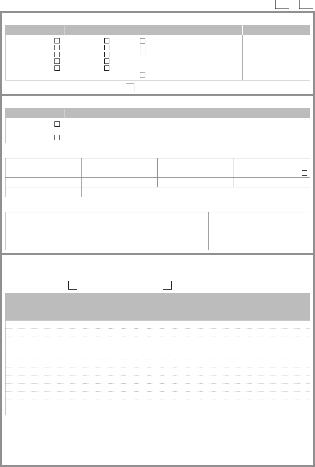
NOTE: This form is suitable for many types of smaller installations not exclusively domestic
OuTCOmES
Acceptable
condition
Unacceptable
condition
State
C1 or C2
Improvement
recommended
State
C3
Not veried
NV
Limitation
lim
Not applicable
N/A
Item
no
Description
Outcome
(Use codes above, provide additional
comment where appropriate.
C1, C2 and C3 coded items to be recorded
in Section K of the Condition Report)
further
investigation
required?
(YES / NO)
1.0 DISTrIbuTOr’S / Supply INTAKE EQuIpmENT
1.1 Service cable condition
1.2 Condition of service head
1.3 Condition of tails – distributor
1.4 Condition of tails – consumer
1.5 Condition of metering equipment
1.6 Condition of isolator (where present)
2.0 prESENCE Of ADEQuATE ArrANgEmENTS fOr SECONDAry Or
AlTErNATIVE SOurCES SuCh AS mICrOgENErATOrS (551.6; 551.7)
3.0 EArThINg / bONDINg ArrANgEmENTS (411.3; chap 54)
3.1 Presence and condition of distributor’s earthing arrangement (542.1.2.1; 542.1.2.2)
3.2 Presence and condition of earth electrode where applicable (542.1.2.3)
3.3 Provision of earthing / bonding labels at all appropriate locations (514.13.1)
3.4 Conrmation of earthing conductor size (542.3; 543.1.1)
3.5 Accessibility and condition of earthing conductor at MET (543.3.2)
3.6 Conrmation of main protective bonding conductor sizes (544.1)
3.7
Condition and accessibility of main protective bonding conductor connections
(543.3.2; 544.1.2)
3.8 Accessibility and condition of all protective bonding connections (543.3.2)
4.0 CONSumEr uNIT(S) / DISTrIbuTION bOArD(S)
4.1 Adequacy of working space / accessibility to consumer unit / distribution board
(132.12; 513.1)
4.2 Security of xing (134.1.1)
4.3 Condition of enclosure(s) in terms of IP rating etc (416.2)
4.4 Condition of enclosure(s) in terms of re rating etc (526.5)
4.5 Enclosure not damaged / deteriorated so as to impair safety (621.2 iii)
4.6 Presence of main linked switch (as required by 537.1.4)
4.7 Operation of main switch (functional check) (612.13.2)
4.8 Manual operation of circuit-breakers and RCDs to prove disconnection (612.13.2)
4.9 Correct identication of circuit details and protective devices (514.8.1; 514.9.1)
4.10 Presence of RCD quarterly test notice present at or near consumer unit / distribution
board (514.12.2)
4.11 Presence of non-standard (mixed) cable colour warning notice at or near consumer
unit / distribution board (514.14)
4.12 Presence of alternative supply warning notice at or near consumer unit / distribution
board (514.15)
4.13 Presence of other required labelling (please specify) (Section 514)
4.14 Examination of protective device(s) and base(s); correct type and rating (no signs of
unacceptable thermal damage, arcing or overheating) (421.1.3)
4.15 Single-pole protective devices in line conductor only (132.14.1; 530.3.2)
4.16 Protection against mechanical damage where cables enter consumer unit /
distribution board (522.8.1; 522.8.11)
4.17 Protection against electromagnetic effects where cables enter consumer unit /
distribution board / enclosures (521.5.1)
4.18 RCD(s) provided for fault protection – includes RCBOs (411.4.9; 411.5.2; 531.2)
4.19 RCD(s) provided for additional protection – includes RCBOs(411.3.3; 415.1)
C-EICR5 REV V1 Aug 2011
CONDITION rEpOrT INSpECTION SChEDulE Sheet of
Sheet of
C-EICR5 REV V1 Aug 2011
OuTCOmES
Acceptable
condition
Unacceptable
condition
State
C1 or C2
Improvement
recommended
State
C3
Not veried
NV
Limitation
lim
Not applicable
N/A
Item
no
Description
Outcome
(Use codes above, provide additional
comment where appropriate.
C1, C2 and C3 coded items to be recorded
in Section K of the Condition Report)
further
investigation
required?
(YES / NO)
5.0 fINAl CIrCuITS
5.1 Identication of conductors (514.3.1)
5.2 Cables correctly supported throughout their run (522.8.5)
5.3 Condition of insulation of live parts (416.1)
5.4 Non-sheathed cables protected by enclosure in conduit, duct or trunking (521.10.1)
• To include the integrity of conduit and trunking systems (metallic and plastic)
5.5 Adequacy of cables for current-carrying capacity with regard for the type and nature
of installation (Section 523)
5.6 Co-ordination between conductors and overload protective devices (433.1; 533.2.1)
5.7 Adequacy of protective devices: type and rated current for fault protection (411.3)
5.8 Presence and adequacy of circuit protective conductors (411.3.1.1; Section 543.1)
5.9 Wiring system(s) appropriate for the type and nature of the installation and external
inuences (Section 522)
5.10
Concealed cables installed in prescribed zones (see Section D: Extent and limitations)
(522.6.101)
5.11 Concealed cables incorporating earthed armour or sheath, or run within earthed
wiring system, or otherwise protected against mechanical damage from nails, screws
and the like (see Section D: Extent and limitations) (522.6.101; 522.6.103)
5.12 Provision of additional protection by RCD not exceeding 30 mA:
• For all socket-outlets of rating 20 A or less provided for use by ordinary persons
unless an exception is permitted (411.3.3)
• For supply to mobile equipment not exceeding 32 A rating for use outdoors
(411.3.3)
• For cables concealed in walls or partitions (522.6.102; 522.6.103)
5.13 Provision of re barriers, sealing arrangements and protection against thermal effects
(Section 527)
5.14 Band II cables segregated / separated from Band I cables (528.1)
5.15 Cables segregated / separated from communications cabling (528.2)
5.16 Cables segregated / separated from non-electrical services (528.3)
5.17
Termination of cables at enclosures – indicate extent of sampling in Section D of the
report (Section 526)
• Connections soundly made and under no undue strain (526.6)
• No basic insulation of a conductor visible outside enclosure (526.8)
• Connections of live conductors adequately enclosed (526.5)
• Adequately connected at point of entry to enclosure (glands, bushes, etc.) (522.8.5)
5.18 Condition of accessories including socket-outlets, switches and joint boxes (621.2(iii))
5.19 Suitability of accessories for external inuences (512.2)
6.0 lOCATION(S) CONTAININg A bATh Or ShOwEr
6.1 Additional protection for all low voltage (LV) circuits by RCD not exceeding 30 mA
(701.411.3.3)
6.2 Where used as a protective measure, requirements for SELV or PELV met
(701.414.4.5)
6.3 Shaver sockets comply with BS EN 61558-2-5 formerly BS 3535 (701.512.3)
6.4 Presence of supplementary bonding conductors, unless not required by
BS 7671:2008 (701.415.2)
6.5 Low voltage (e.g. 230 volts) socket-outlets sited at least 3 m from zone 1 (701.512.3)
6.6 Suitability of equipment for external inuences for installed location in terms of IP
rating (701.512.2)
6.7 Suitability of equipment for installation in a particular zone (701.512.3)
6.8 Suitability of current-using equipment for a particular position within the location (701.55)
7.0 OThEr pArT 7 SpECIAl INSTAllATIONS Or lOCATIONS
7.1 List all other special installations or locations present, if any (record separately the
results of particular inspections applied).
Tested by:
Name (CApITAlS) .......................................................... Signature .......................................................... Date .....................................
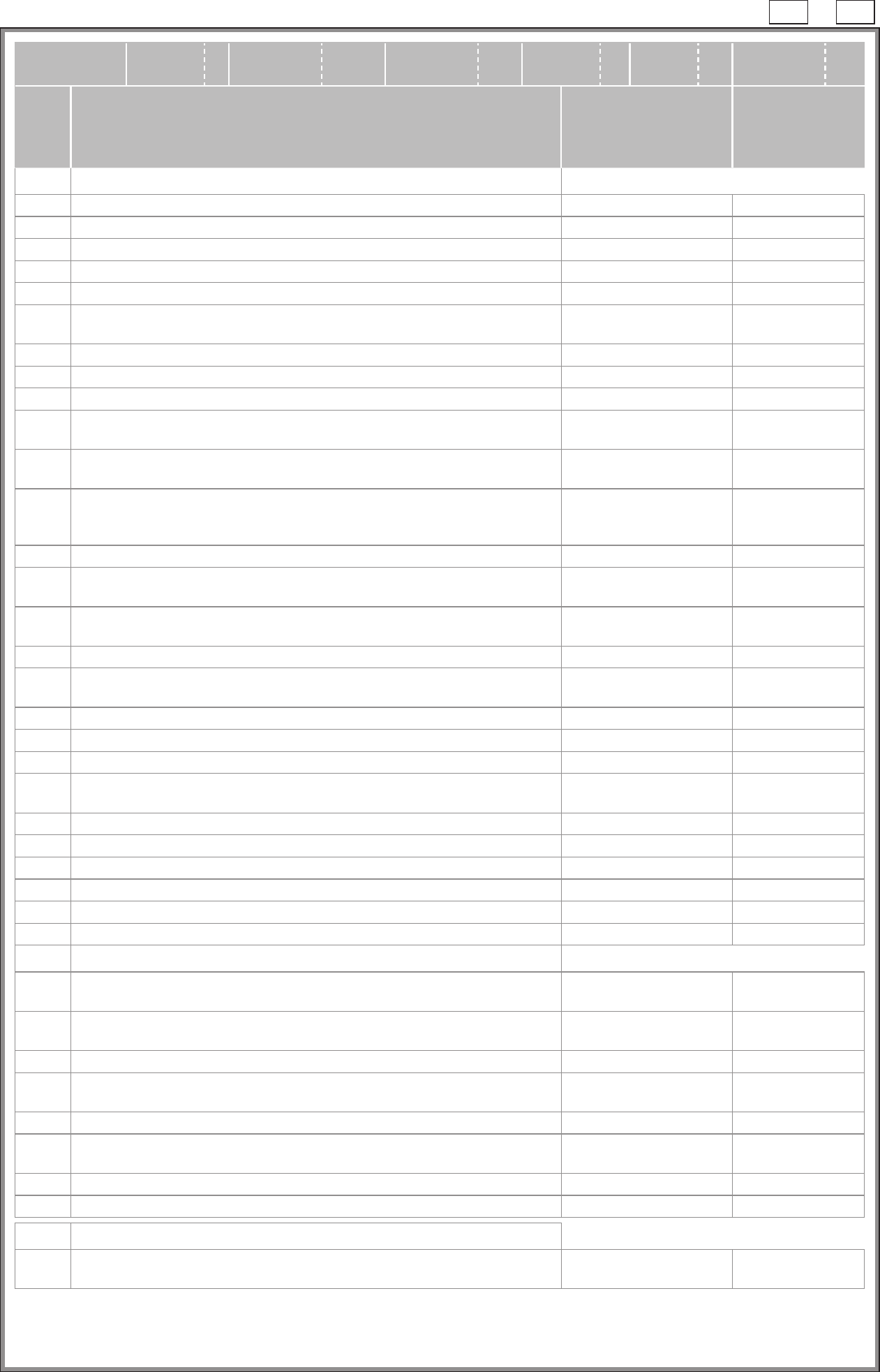
Schedule of teSt reSultS Sheet of
DB Reference no. .......................................................................................
Location ......................................................................................................
Zs at DB (Ω) ...............................................................................................
I
pf
at DB (kA) ...............................................................................................
Correct polarity of supply conrmed YES / NO
Phase sequence conrmed (where appropriate)
Details of circuits and/or installed equipment vulnerable to damage when testing
.................................................................................................................................
.................................................................................................................................
.................................................................................................................................
.................................................................................................................................
.................................................................................................................................
Details of test instruments used (state serial and/or asset numbers)
Continuity ......................................................................................................
Insulation resistance .....................................................................................
Earth fault loop impedance ...........................................................................
RCD ..............................................................................................................
Earth electrode resistance ............................................................................
tested by:
Name (capitalS)...............................................................................................................................
Signature........................................................................ date ..........................................................
test results
Ring nal circuit
continuity (Ω)
Continuity (Ω)
(R
1
+ R
2
) or R
2
Insulation
resistance
(MΩ)
Polarity
Z
s
(Ω)
RCD
(ms)
Remarks
(continue on a
separate sheet if
necessary)
circuit details
Overcurrent device Conductor details
Circuit number
Circuit description
BS (EN)
Type
Rating (A)
Breaking
capacity (kA)
Reference
method
Live (mm
2
)
cpc (mm
2
)
r
1
(line)
r
n
(neutral)
r
2
(cpc)
(R
1
+ R
2
) *
R
2
Live – Live
Live – E
Ω
@I
∆
n
@5I
∆
n
Test button
operation
A B C D E F G H I J K L M N O P Q R S T U V
* Where there are no spurs connected to a ring nal circuit this value is also the (R
1
+ R
2
) of the circuit.
C-STR REV Aug 2011 V1
CONDITION rEpOrT
guIDANCE fOr rECIpIENTS
(to be appended to the report)
This report is an important and valuable document which should be retained for future reference.
1 The purpose of this Condition Report is to conrm, so far as reasonably practicable, whether or not the electrical
installation is in a satisfactory condition for continued service (see Section E). The Report should identify any damage,
deterioration, defects and/or conditions which may give rise to danger (see Section M).
2 The person ordering the Report should have received the original Report and the inspector should have retained a
duplicate.
3 The original Report should be retained in a safe place and be made available to any person inspecting or undertaking
work on the electrical installation in the future. If the property is vacated, this Report will provide the new owner/occupier
with details of the condition of the electrical installation at the time the Report was issued.
4 Where the installation incorporates residual current devices (RCDs) there should be a notice at or near the devices
stating that they should be tested regularly. for safety reasons it is important that these instructions are followed.
5 Section D (Extent and Limitations) should identify fully the extent of the installation covered by this Report and any
limitations on the inspection and testing. The inspector should have agreed these aspects with the person ordering the
Report and with other interested parties (licensing authority, insurance company, mortgage provider and the like) before
the inspection was carried out.
6 Some operational limitations such as inability to gain access to parts of the installation or an item of equipment may have
been encountered during the inspection. The inspector should have noted these in Section D.
7 For items classied in Section K as C1 (‘Danger present’),
the safety of those using the installation is at risk, and it
is recommended that a competent person undertakes the necessary remedial work immediately.
8 For items classied in Section K as C2 (‘Potentially dangerous’),
the safety of those using the installation may be at
risk, and it is recommended that a competent person undertakes the necessary remedial work as a matter of urgency.
9 Where it has been stated in Section K that an observation requires further investigation, the inspection has revealed
an apparent deciency which could not, due to the extent or limitations of this inspection, be fully identied. Such
observations should be investigated as soon as possible. A further examination of the installation will be necessary, to
determine the nature and extent of the apparent deciency (see Section F).
10 For safety reasons, the electrical installation should be re-inspected at appropriate intervals by a competent person. The
recommended date by which the next inspection is due is stated in Section F of the Report under ‘Recommendations’
and on a label near to the consumer unit / distribution board.
CONDITION rEpOrT
guIDANCE fOr ThE INSpECTOr
This report is an important and valuable document which should be retained for future reference.
1 Section 1. Where inadequacies in the distributor’s equipment are present, the inspector should advise the person
ordering the work to inform the appropriate authority.
2 Older installations designed prior to BS 7671:2008 are unlikely to have been provided with RCDs for additional protection.
The absence of such protection should, as a minimum, be given a code C3 classication (item 5.12).
3 This schedule is not exhaustive.
4 Numbers in brackets are Regulation references to specied requirements.